But first, a quick description of the device under test (DUT): Anisca Bird consists of a wooden perch that can be mounted in front of the entrance of barn owl nest boxes. It is smart because it contains an integrated weight sensor as well as a low frequency RFID reader which detects a passive identification ring attached to the observed owl's leg. Every time an owl visits its nest box, our device detects the owl's identity, measures its weight, and transmits this data using a low-power wireless standard called SIGFOX.
When they are active, the RFID reader and the SIGFOX transceiver emit electromagnetic signals at 125 kHz and 868 MHz, respectively. Because of imperfections, they also radiate unwanted, so-called spurious emissions, at other frequencies, even when they are not actively transmitting a signal. Because these radio waves could potentially interfere with other electronic devices, such as laptops, dishwashers or even cars, norms and standards were established to limit the power of both main and spurious emissions of any electronic device.
The most relevant norms for our tests are ETSI EN 300 330 for the RFID reader and ETSI EN 300 220-2 for SIGFOX. Referring to these documents ahead of the measurements, we prepared our prototype such that both radios can be turned on and off manually by sending commands through the available USB port of the DUT. We also build a wooden holder onto which we can mount the smart perch during the tests. It is important that this holder is completely non-metallic, as metal objects could interfere with the antennas and therefore falsify the measurements.

Then the actual measurements started in our partner lab’s anechoic chamber – this is a room that is completely shielded from any radio signals in our environment (e.g. wireless LAN, mobile phones, etc…) and has its walls covered with non-reflective structures. The prototype and on it, an RFID bird ring, was then placed on a rotating turn table. Using the USB service port, we turned on the RFID reader in continuous wave (CW) mode, such that it transmits a constant 125 kHz signal. This signal was then picked up by a wide-band H-field antenna (which is just a very large circular coil), and, using a spectrum analyzer, the magnetic field strength could be plotted across the entire frequency range from 10 kHz to 30 MHz. This measurement was repeated for every possible orientation of the DUT, using the turntable, and also by placing it sideways.
For frequencies above 30 Mhz until 1 GHz, the receiving antenna was replaced with a “far-field” antenna, which is more sensitive to the electrical field emitted at those frequencies. In both frequency ranges, measurements were also performed with the DUT in standby mode (i.e. with the RFID reader being turned off).
Lastly, the same types of measurements were performed with the SIGFOX module active for the range of 30 MHz all the way up to 6 GHz.
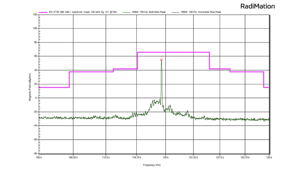
Let’s look at some of the results of these tests. In the figure below, the magnetic field strength of the RFID reader in active mode is plotted in green. A distinct peak is visible close to its intended frequency of operation: 125 kHz. The pink line is an envelope that describes the maximum allowed field strength of an LF RFID device according to the respective norm, which the DUT is respecting.
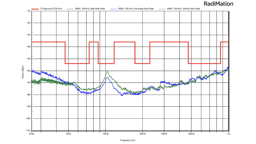
In the next figure, we are looking at spurious emissions of the DUT again with the RFID reader on, but between 30 MHz and 1 GHz. The limits for spurious emissions – here in red – are much lower, as these are unwanted emissions that should be avoided as good as possible by applying good electronic design practices. We can see a slight peak at 100 MHz, which we concluded comes from the internal voltage converter of the DUT that provides a regulated 5V supply to the RFID reader. However, as the peak is still below the required limit, this is not a concern.
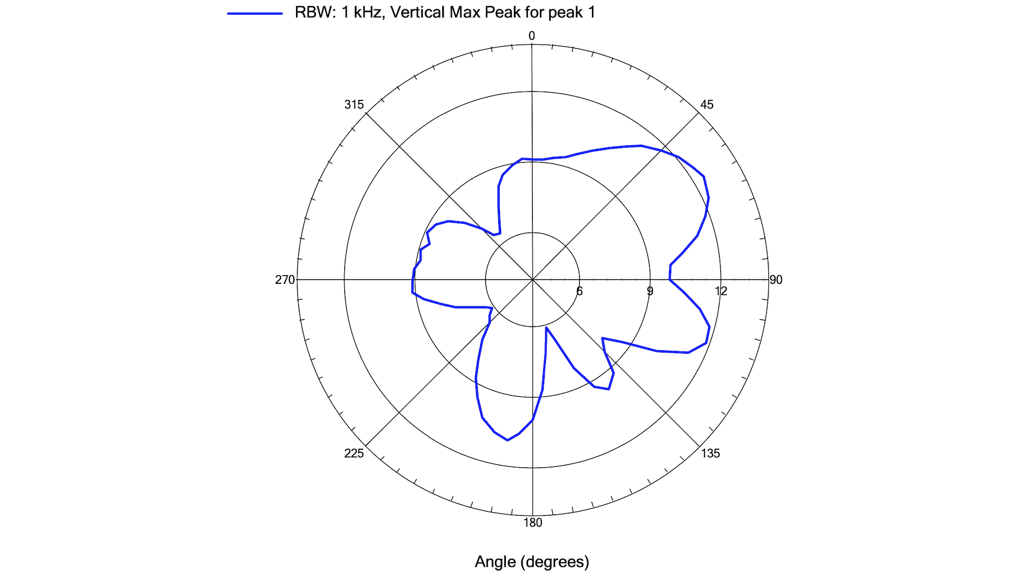
Similar results were achieved for the SIGFOX emissions, with all of them respecting the given norms as well. But while for the previous measurements we simply kept the maximum emission strength of all orientations in 3 dimensions of the DUT, an additional result was produced for the SIGFOX signal: the radiation pattern of the antenna. We see below that the antenna doesn’t radiate equally strongly towards all directions. Even though the antenna itself is isotropic (i.e. by design has a uniform emission strength into all directions), it no longer performs as such when it becomes part of a system because it is mounted in vicinity of cables and the aluminum case. Most importantly however, in none of the directions the signal strength crossed the maximum allowed power limits (in this case 14 dBm or 25 mW e.r.p.).
With all emission tests passed, we are now confident to launch production of the first batch of owl weight trackers for the Swiss Ornithological Institute (Vogelwarte Sempach) and we can’t wait to see the first owl visits to arrive in our database!